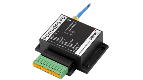
PCAN-GPS FD
Regular price£380.00 Sale price Pricing excludes VAT.Shipping cost calculated in checkout.
- Message us via the chat bubble (Mon–Fri, 9–5)
- Or give us a call on +44 (0) 1234 247176
Technical Specifications
- NXP LPC54618 microcontroller with Arm® Cortex® M4 core
- High-speed CAN connection (ISO 11898-2)
- Complies with CAN specifications 2.0 A/B and FD
- CAN FD bit rates for the data field (64 bytes max.) from 40 kbit/s up to 10 Mbit/s
- CAN bit rates from 40 kbit/s up to 1 Mbit/s
- NXP TJA1043 CAN transceiver
- CAN termination can be activated through solder jumpers
- Wake-up by CAN bus or by separate input
- Receiver for navigation satellites u-blox MAX-M10S
- Supported navigation and supplementary systems: GPS, Galileo, BeiDou, GLONASS, SBAS, and QZSS
- Simultaneous reception of 4 navigation systems
- 3.3 V supply for active GPS antennas
- Electronic three-axis magnetic field sensor IIS2MDC from ST
- Gyroscope and three-axis accelerometer ISM330DLC from ST
- 8 MByte QSPI flash
- 3 digital I/Os, each usable as input (High-active) or output with Low-side switch
- LEDs for status signaling
- Connection via a 10-pole terminal strip (Phoenix)
- Voltage supply from 8 to 32 V
- Button cell for preserving the RTC and the GPS data to shorten the TTFF (Time To First Fix)
- Extended operating temperature range from -40 to +85 °C (with exception of the button cell)
- New firmware can be loaded via CAN interface


Programmable Sensor Module with CAN FD Connection
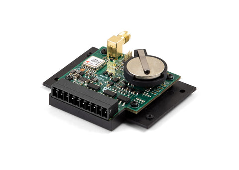
The PCAN-GPS FD is a programmable sensor module for position and orientation determination with CAN FD connection. It has a satellite receiver, a magnetic field sensor, an accelerometer, and a gyroscope. Incoming sensor data is processed by the NXP microcontroller LPC54618 and then transmitted via CAN or CAN FD.
The behavior of the PCAN-GPS FD can be programmed freely for specific applications. The firmware is created using the included development package with GNU compiler for C and C++ and is then transferred to the module via CAN. Various programming examples facilitate the implementation of own solutions.
On delivery, the PCAN-GPS FD is provided with a standard firmware that transmits the raw data of the sensors periodically on the CAN bus.
Requirements
The transfer of the firmware via CAN requires a PEAK CAN interface.
Scope of Supply
- PCAN-GPS FD in plastic casing including mating connector (Phoenix Contact FMC 1,5/10-ST-3,5 - 1952348)
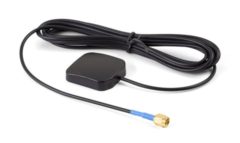
- External antenna for satellite reception
- Windows® development package with GCC ARM Embedded and programming examples
- Flash program PEAK-Flash for Windows® 11 (x64/ARM64), 10 (x64) Details ...
- Manual in PDF format
Technical Specifications
- NXP LPC54618 microcontroller with Arm® Cortex® M4 core
- High-speed CAN connection (ISO 11898-2)
- Complies with CAN specifications 2.0 A/B and FD
- CAN FD bit rates for the data field (64 bytes max.) from 40 kbit/s up to 10 Mbit/s
- CAN bit rates from 40 kbit/s up to 1 Mbit/s
- NXP TJA1043 CAN transceiver
- CAN termination can be activated through solder jumpers
- Wake-up by CAN bus or by separate input
- Receiver for navigation satellites u-blox MAX-M10S
- Supported navigation and supplementary systems: GPS, Galileo, BeiDou, GLONASS, SBAS, and QZSS
- Simultaneous reception of 4 navigation systems
- 3.3 V supply for active GPS antennas
- Electronic three-axis magnetic field sensor IIS2MDC from ST
- Gyroscope and three-axis accelerometer ISM330DLC from ST
- 8 MByte QSPI flash
- 3 digital I/Os, each usable as input (High-active) or output with Low-side switch
- LEDs for status signaling
- Connection via a 10-pole terminal strip (Phoenix)
- Voltage supply from 8 to 32 V
- Button cell for preserving the RTC and the GPS data to shorten the TTFF (Time To First Fix)
- Extended operating temperature range from -40 to +85 °C (with exception of the button cell)
- New firmware can be loaded via CAN interface