| Functionality |
The device produces analog/digital/pulse measurements from 8 input channels and outputs signals via CAN |
| Included |
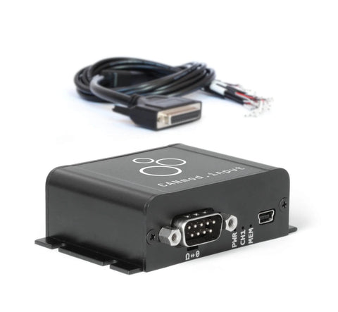
CANmod.input module and USB dust cover (input sensors and mini USB adapter not included) |
| Firmware |
Supports free firmware updates via USB for adding features |
| Configuration |
Configuration files based on the popular open source JSON schema concept (similar to the CANedge) |
| Software |
Free open source editor tool for easy device configuration (offline/online version available) |
| Safety |
CE, FCC, IC and RoHS certified (see the Docs for certificates) |
| Warranty |
1-year warranty |
| Support |
Free, fast & high quality support
|
| Origin |
Denmark |
| Channels |
Supports 8 input channels |
| Sensor Types |
All 8 input channels support analog, digital and pulse-type sensors |
| Sampling Method |
Each input channel samples both the analog, digital and pulse signal of the connected sensor |
| Input Range |
Configurable input ranges (0-10V, 0-5V, 0-2.5V, 0-1.25V, 0-0.625V) |
| |
Range modification is useful e.g. for optimizing quantization resolution and signal amplification |
| |
The input channels share input ranges in pairs of two (CH1/CH2, CH3/CH4, CH5/CH6, CH7/CH8) |
| Resolution |
10 bit |
| Sampling Frequency |
Analog inputs: 1 kHz | Digital: 1 kHz | Pulse (frequency/counter): 16 kHz |
| Digital Thresholds |
Configurable digital high/low switch thresholds (0-100%) incl. optional dead-zone/hysteresis |
| Pulse Modes |
Pulse inputs can be measured as frequencies (reset) or counters (accumulate) |
| Pulse Resolution |
Up to 32 bit (4,294,967,294) |
| Protection |
Sensor inputs are protected against overvoltage & undervoltage conditions |
| Input Impedance |
136K |
| CAN Signals |
The module ouputs sensor data via CAN messages/signals (for a full list, see the Docs or DBC file) |
| |
Analog measurements are output in millivolt (mV) [1000 Hz] |
| |
Digital measurements are output as 'actual' (dead-zone, low, high) and 'low'/'high' signals [1000 Hz] |
| |
Pulse measurements are output as a frequency/counter value (for reset/accumulate mode) [1000 Hz] |
| |
Note: Limits apply to the practical output frequency depending on baud rate, message count etc. |
| Channels |
1 x CAN channel |
| Modes |
The device can either broadcast the data onto the CAN bus - or provide it on-request |
| Standard |
ISO 11898: Compliant with CAN (between 5K and 1 Mbit/s baud rates) and CAN FD (1M, 2M, 4M) |
| Identifiers |
Compliant with CAN specifications 2.0A (11-Bit ID) and 2.0B (29-Bit ID) |
| Termination |
Termination can be toggled via switch below DB9 connector |
| Retransmission |
Retransmission of frames that have lost arbitration or been disturbed by errors |
| Transceiver Protection |
Protection: +/- 25kV HBM ESD, +/-12kV IEC ESD, +/-14 V bus fault, short circuit |
| |
Common mode input voltage: +/-12V |
| |
TXD dominant timeout (prevents network blocking in the event of a failure) |
| Bit Rate |
Select between standard bit rates (5K to 1M) or use custom bit-timing |
| Enable/Disable |
Individually enable/disable each CAN message |
| Identifier Customization |
Individually configure each CAN ID (11-bit or 29-bit) |
| Push/Poll Mode |
Individually configure 'trigger' modes for each CAN message (push or poll) |
| Frequency |
Individually configure prescaling of each CAN message frequency to lower rates |
| Input Supply |
+5V to +26V DC via the DB9 connector (power via pin 1 or pin 9) |
| Power Consumption |
Extremely low (<1W) - no risk of battery drainage |
| Protection |
Reverse voltage protection on CAN-bus supply |
| |
Transient voltage event protection on supply lines |
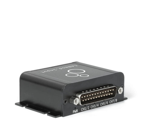
| Enclosure & Weight |
Compact aluminium enclosure: 52.5 x 70.0 x 24.5 mm (L x W x H), 70 grams |
| Connector (Front) |
1 x Standard D-sub 9 (DB9) connector |
| Connector (Back) |
1 x D-sub 25 (DB25) connector |
| Sensor Supply |
Dedicated excitation signals for each channel (~3.3 V, shared max of 100 mA) |
| Pin-Out |
See the product manual for the DB9/DB25 connector pin-outs |
| USB |
Standard mini USB connector for config/firmware updates and streaming (USB cable not included) |
| LEDs |
Module status via 8 external LEDs: Power, CAN bus, Memory, CH1/CH2, CH3/CH4, CH5/CH6, CH7/CH8 |
| Temperature |
Operating temperature (CANmod.input module): -25degC to +70degC |
| IP Rating |
IP Rating 40 |
| Mounting |
Module can be mounted via e.g. rugged double-sided tape, zip-ties or a mounting bracket
|