

What Is CAN Bus? A Practical Guide for Engineers
What is CAN Bus?
CAN Bus (Controller Area Network) is a communication system that allows electronic devices to exchange data over a shared network. It’s widely used in vehicles, machinery and industrial systems where multiple devices need to communicate reliably.
Modern systems can contain dozens, sometimes hundreds, of small computers called Electronic Control Units (ECUs). Each ECU has a specific job, from controlling a vehicle’s brakes and airbags to managing a robot arm on a factory floor.
CAN Bus provides a simple and robust way for these devices to communicate without needing separate connections between every component.
Originally developed for the automotive industry in the 1980s, CAN has since become one of the most widely used communication standards across engineering, thanks to its reliability, simplicity and relatively low cost.
At Control Technologies, we help organisations design, implement, and maintain CAN bus systems. We also provide the essential hardware and software tools that engineers need:
- CAN bus interfaces & adapters
- CAN bus analysis software
- Data loggers & analyzers
-
Automation solutions
-
Digitalisation platforms
This guide will take you through everything you need to know about CAN bus: what it is, how it works, its history, benefits, variants, and how to log and analyze CAN bus data.
P.S. If you’re looking for a more detailed guide about how to implement CAN-Bus in your next machine build, download our guide: “A Machine Builder’s Guide to CAN-Bus“
What Does CAN Bus Stand For?
The term CAN bus can be broken down into:
-
CAN (Controller Area Network) → the communication protocol itself.
- Bus → the shared two-wire communication pathway that links devices together.
In other words, the meaning of CAN Bus is simply “a Controller Area Network that allows electronic devices to communicate efficiently over a shared two-wire system.”
Instead of running separate wiring between every ECU, CAN bus allows multiple devices to share one network.

In simple terms: CAN bus protocol is like a group chat for machines. Each ECU can broadcast messages to all others at once, with built-in rules to ensure important messages are heard first.
A short history of CAN Bus
As vehicles became more electronically complex in the 1980s, manufacturers faced a growing problem: more electronic systems meant more wiring, greater weight and increasingly complicated communication between components.
Bosch began developing CAN in 1983 as a way for electronic control units to communicate over a shared network, reducing the need for dedicated point-to-point wiring.
- 1983: Bosch began development of CAN.
- 1986: CAN was introduced at the SAE conference in Detroit.
- 1987: Intel and Philips released the first CAN controller chips.
- 1991: The Mercedes-Benz W140 S-Class became the first production car to use CAN.
What began as a solution to increasing complexity in automotive electronics has since developed into a widely adopted communication standard across engineering.
Today, CAN is used in applications ranging from passenger and commercial vehicles to industrial automation, off-highway machinery, marine systems and medical equipment. Its reliability, relatively simple architecture and extensive ecosystem have helped it remain relevant even as the systems around it have become considerably more sophisticated.
How Does CAN Bus Work?
At its simplest, CAN allows multiple electronic devices to share information over the same two-wire network.
Each device, or node, can transmit messages onto the network. Every other node can see those messages and decide which ones are relevant to it.
Rather than messages being addressed directly to individual devices, each CAN message carries an identifier that describes the information it contains. This identifier also determines the message's priority if multiple devices try to communicate at the same time.
CAN also includes built-in error detection, helping devices communicate reliably even in electrically noisy environments.
To understand how this works in practice, it helps to look at the physical network and the messages being transmitted across it.
The Electrical Layer
A CAN bus system uses just two twisted wires:
-
CAN High (CAN_H)
-
CAN Low (CAN_L)
 A CAN cable: CAN_H and CAN_L twisted together inside a single sheath.
These wires transmit differential signals. Instead of sending a single voltage level (which is vulnerable to noise), CAN transmits two opposite signals and compares them. This makes the system extremely robust in electrically noisy environments like vehicles and factories.

CAN uses differential signalling: during a dominant bit, CAN_H rises while CAN_L falls. The receiver measures the voltage difference between the two signals, helping common electrical interference to cancel out.
Message-Based Communication
CAN is a message-based protocol. Devices don't normally send a message directly to a specific recipient. Instead, a node transmits a message onto the shared network and every other node can see it.
Each message carries an identifier that tells the network what type of message it is and also determines its priority.
Individual nodes are configured to recognise the messages that matter to them and ignore those that don't.
For example, a controller might transmit a message containing an engine speed value. Any other device that needs that information can receive and use it without the transmitting controller having to address each recipient individually.
CAN Bus Frame Structure
CAN doesn't transmit information as a continuous stream of data. Instead, communication is organised into frames: structured messages transmitted across the network.
The most common is the Data Frame, which contains the information being shared between devices.
A typical Classical CAN Data Frame includes:
- Identifier (ID) – identifies the message and determines its priority.
- Data – the information being transmitted, with up to 8 bytes in Classical CAN.
- Control information – provides information about the frame and its contents.
- Error checking – allows receiving nodes to detect transmission errors.
- Acknowledgement – confirms that the frame has been received successfully.
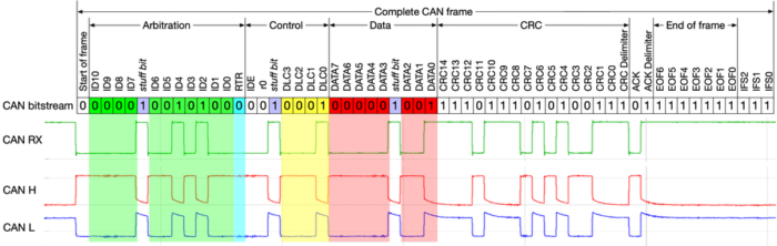
CAN also defines other frame types for functions such as requesting data and signalling communication errors. CAN FD extends the amount of data that can be carried in a frame to up to 64 bytes and supports higher data rates.
Arbitration: Resolving Conflicts
Because CAN uses a shared network, more than one node may attempt to transmit at the same time. CAN handles this using a process called bitwise arbitration.
The identifier within each CAN frame determines its priority. If two nodes begin transmitting simultaneously, they monitor the bus as they transmit their identifiers.
The message with the lower numerical identifier has the higher priority and continues transmitting. The other node stops transmitting and waits until the bus becomes available again.
Importantly, this happens without corrupting the higher-priority message.
This allows engineers to design networks so that time-critical messages receive priority over less important traffic.

Error Detection & Fault Tolerance
Reliability is built into the CAN protocol. Each transmitted frame includes mechanisms that allow nodes to detect communication errors and respond when something goes wrong.
These include:
- CRC checks (Cyclic Redundancy Check) – help detect whether data has been corrupted during transmission.
- Acknowledgement (ACK) – allows receiving nodes to confirm that a valid frame has been received.
- Error Frames – signal to other nodes that an error has been detected.
- Automatic retransmission – allows affected messages to be transmitted again when appropriate.
CAN nodes also maintain internal error counters. If a device repeatedly causes communication problems, its participation in the network can progressively be restricted. Eventually, a severely faulty node can enter a bus-off state, preventing it from continuing to disrupt communication for the rest of the network.
These mechanisms are a major reason CAN has become so widely used in applications where reliable communication in demanding electrical environments is essential.
Benefits of CAN Bus
Reduced Wiring Complexity
CAN bus allows multiple electronic control units (ECUs) to communicate over the same two-wire network, rather than requiring dedicated wiring between every device. This significantly reduces wiring complexity, weight and installation costs, particularly as the number of connected devices increases.
Robust and Reliable
CAN was designed to operate reliably in electrically noisy environments. Differential signalling helps protect communications against electromagnetic interference, while built-in error detection and handling mechanisms help identify transmission problems and maintain network integrity.
Prioritisation of Messages
CAN uses message-based arbitration to determine which message is transmitted when multiple nodes attempt to communicate at the same time. Higher-priority messages gain access to the bus first, allowing time-critical information to be transmitted without collisions disrupting the network.
Scalability
Additional devices can be added to an existing CAN network without requiring individual communication links between every component. This makes CAN well suited to systems that need to evolve or incorporate additional sensors, controllers and other devices over time.
Cost-Efficiency
Using a shared communication bus reduces the amount of cabling, connectors and associated hardware required within a system. Combined with the widespread availability of CAN-compatible components and tools, this can reduce both system complexity and overall implementation costs.
Wide Adoption & Longevity
CAN has been widely adopted across automotive, industrial automation, off-highway, marine, medical and other engineering applications. Its established standards, extensive hardware ecosystem and continued development through technologies such as CAN FD make it a well-supported choice for long-term projects.
Variants of CAN Bus
CAN has evolved since its introduction in the 1980s, with newer variants developed to support higher data rates and larger payloads while retaining the core principles of the original protocol.
The main variants you'll encounter are Classical CAN, CAN FD and CAN XL.
Classical CAN (CAN 2.0A/B)
- Introduced in the 1980s
- Supports up to 1 Mbit/s
- 11-bit (2.0A) or 29-bit (2.0B) identifiers
- 8-byte data payload
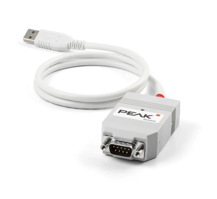
👉 Buy the PEAK P-CAN USB from the Control Tech UK Webshop
CAN FD (Flexible Data-Rate)
- Introduced in 2012
- Up to 64-byte data payload
- Allows switching to higher bitrates during transmission
- Backward-compatible with Classical CAN
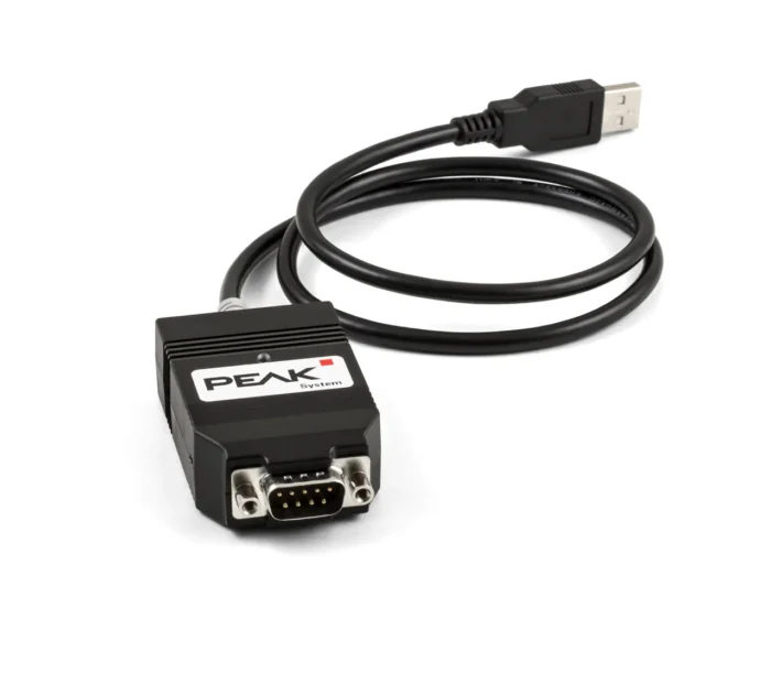
👉 Buy the PEAK P-CAN USB FD from the Control Tech UK Webshop
CAN XL
- Still emerging
- Supports up to 20 Mbit/s
- Payloads up to 2,048 bytes
- Designed for next-generation vehicles, automation, and IoT
👉 Buy the PEAK P-CAN USB XL from the Control Tech UK Webshop

CAN Bus Variants, Comparison Table

Higher-Level CAN Protocols
CAN defines how messages are transmitted reliably between devices, but it doesn't necessarily define what the data inside those messages means.
For this, many CAN-based systems use a higher-level protocol. These add additional rules and conventions that define how devices communicate and how information is structured and interpreted.
Common examples include:
CANopen
Widely used in industrial automation, machinery and embedded control systems. CANopen provides standardised methods for device communication and configuration.
J1939
Commonly used in heavy-duty vehicles, agricultural machinery and off-highway equipment. J1939 defines how information such as engine speed, temperatures and diagnostic information is communicated over CAN.
NMEA 2000
A CAN-based protocol used in marine applications to allow equipment such as engines, sensors, displays and navigation systems to exchange information.
ISOBUS
Used in agricultural machinery to standardise communication between tractors, implements and other equipment.
Many manufacturers also use their own proprietary CAN protocols, where the meaning and structure of CAN messages are defined specifically for their system.
In simple terms, CAN provides the communication mechanism; the higher-level protocol provides many of the rules that give the data meaning.
Applications of CAN Bus Protocol
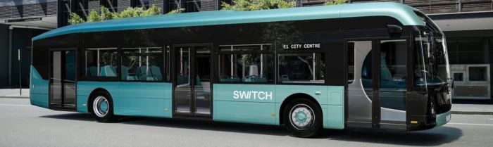
Automotive
- Engine management
- Transmission control
- ABS and stability systems
- Airbags and safety systems
- EV battery management
- Infotainment
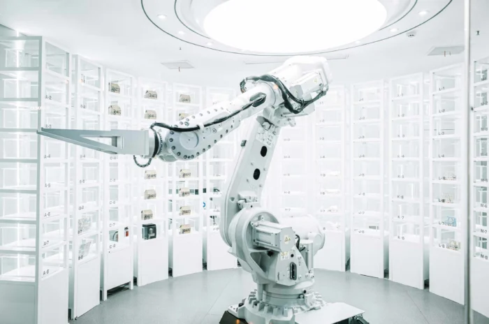
Industrial Automation
- PLCs and robotic systems
- Motor control and drives
- Factory monitoring systems
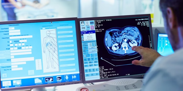
Medical
- Prosthetics
- Scanners and imaging
- Life-support devices
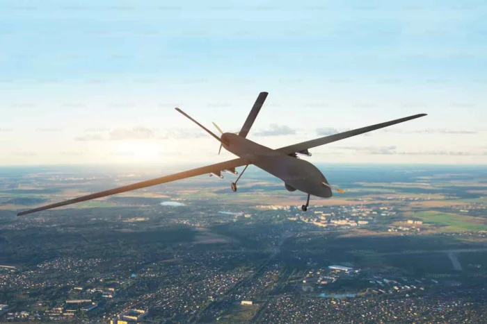
Aerospace & Marine
- Navigation systems
- Flight control
- Marine engine monitoring
Smart Infrastructure
- Elevators and lifts
- Building management
- Energy optimisation
👉 Explore our automation solutions and digitalisation tools to see how CAN bus can be integrated into your industry.
How to Log CAN Bus Data
CAN bus data logging allows engineers to capture the messages being transmitted across a CAN network so they can be stored and analysed later. It's commonly used for diagnostics, development, testing, validation and monitoring systems in real-world operation.
The exact setup will depend on whether you're analysing a network at a desk or recording data remotely in a vehicle or machine, but the basic process is similar.
Steps:
1. Connect to a CAN network
First, you'll need a way of accessing the CAN bus.
For development and diagnostics at a PC, this will typically be a CAN bus interface, which connects your computer to the CAN network via USB, Ethernet or another connection.
For unattended or in-field recording, a dedicated CAN data logger can capture traffic without requiring a PC to remain connected.
Your interface will need to be connected to the appropriate CAN High, CAN Low and, where required, ground connections on the network.
2. Configure the connection
Before you can reliably capture traffic, the interface or logger needs to be configured to match the network.
One of the most important settings is the bit rate. Classical CAN networks commonly operate at rates such as 125, 250, 500 kbit/s or 1 Mbit/s, although the correct setting depends on the system you're connecting to.
For CAN FD networks, the arbitration and data-phase bit rates also need to be configured correctly.
If these settings don't match the network, you may see communication errors or be unable to receive meaningful traffic.
3. Capture the CAN traffic
Once connected and configured, the interface or logger can begin recording CAN frames travelling across the network.
Depending on your setup, the captured data may include information such as:
- CAN identifier
- timestamp
- data length
- payload/data bytes
- frame type
- CAN channel
At this stage you're looking at the raw CAN traffic. You can see which messages are being transmitted and how frequently they appear, but the data bytes themselves don't necessarily tell you what the information represents.
4. Decode and interpret the data
The next step is turning the raw CAN messages into useful engineering information.
CAN bus software can be used to filter, inspect, transmit and analyse CAN traffic. Where a database or protocol definition is available, the raw bytes can also be translated into meaningful signals such as temperature, pressure, speed or device status.
For networks using higher-level protocols such as CANopen or J1939, appropriate tools can help interpret the protocol-specific information carried within CAN messages.
Without a database or known protocol, engineers may instead analyse the raw messages directly to understand how the system is communicating.
5. Analyse and troubleshoot
Once the data has been captured, it can be examined to understand network behaviour or investigate a particular problem.
For example, an engineer might compare logs from a system when it is operating normally with data captured when a fault occurs. Message timing, missing messages, unexpected values or changes in network behaviour can then help narrow down the cause.
Longer-term logging can also reveal intermittent problems that may be difficult to reproduce during a workshop or bench test.
👉 View our range of CAN-Bus loggers at the Control Tech UK Webshop
Why log CAN bus data?
CAN logging gives engineers a record of what happened on a network and when, making it useful throughout development, testing and troubleshooting.
Common applications include:

CAN Bus Interfaces, Analysers & Data Loggers
Although these tools are sometimes grouped together, they perform slightly different jobs.
CAN bus interfaces connect a computer to a CAN network. They're ideal for development, commissioning and diagnostics where an engineer wants to interact with the network in real time.
CAN data loggers record CAN traffic for later analysis, often without requiring a computer to remain connected. This makes them particularly useful for field testing, vehicles, machinery and intermittent fault investigation.
CAN analysis software allows engineers to view, filter, interpret and analyse the traffic captured through an interface or logger. More advanced tools can also transmit messages, decode signals, automate tests and work with higher-level protocols.
👉 Explore Control Tech UK’s ranges of CAN tools:
The Future of CAN Bus

Despite being developed more than 40 years ago, CAN bus remains an important communications technology across automotive, industrial, off-highway and many other engineering applications.
Rather than being replaced outright, CAN continues to evolve alongside newer networking technologies. Developments such as CAN FD and CAN XL increase the amount of data that can be transferred and support higher data rates, extending CAN into applications with greater communication demands.
CAN and Ethernet working together
The future isn't necessarily a choice between CAN and Ethernet.
As vehicles, machines and industrial systems become more connected and data-intensive, different networking technologies can be used for different jobs within the same system. Ethernet can provide high-bandwidth communication, while CAN remains well suited to reliable, real-time communication between controllers, sensors and other embedded devices.
This means engineers are increasingly likely to encounter hybrid network architectures containing both CAN-based networks and Ethernet.
Increasing focus on cybersecurity
Traditional CAN was designed for reliable communication between trusted devices, rather than today's highly connected systems.
As vehicles and machines become connected to external networks, cloud platforms and remote services, cybersecurity is becoming an increasingly important consideration. Protecting gateways, controlling access to networks and monitoring unexpected communication will therefore form an important part of future CAN system design.
Connected machines and digitalisation
CAN data is also becoming useful beyond the network itself.
Information generated by controllers and sensors can be collected through gateways and data loggers and passed into wider monitoring, analytics and digitalisation platforms. This allows organisations to use operational CAN data for applications such as remote monitoring, predictive maintenance, performance analysis and fleet or machine management.
CAN therefore increasingly acts as one part of a much larger connected engineering system.
An established technology that continues to evolve
CAN's longevity is one of its strengths. Engineers have access to a mature ecosystem of controllers, interfaces, software, development tools and expertise, while newer standards continue to extend what CAN-based networks can achieve.
For engineers, the important question is increasingly not simply “CAN or something newer?”, but which combination of networking technologies best suits the requirements of the application.
👉 Learn how CAN bus fits into Industry 4.0 in our digitalisation solutions.
Engineering Services from Control Technologies

At Control Technologies, we don't just supply CAN hardware and software. Our engineers design, develop, integrate and troubleshoot CAN systems for real-world applications.
Whether you need help designing a new CAN network, integrating devices into an existing system or diagnosing a problem that isn't behaving as expected, our engineering team can help.
👉 Visit our Engineering Support page to see how our team can help.


